
Start with a drawing with Contours and a TIN file

Draw a 2d polyline (2DP) along the course you want to profile.

Use Reverse Polyline (RP, RevPline) to make sure the arrows point from the start to the end.


Add the TIN - the Tile Quadrangle. If your line passes through two, we need to merge - instructions to follow hopefully with a link here.
For a simple profile, just go with the middle. Beware of Railroad centerlines.

If there is not a PROFILE folder in the project, add one.

Use a logical name. Be sure to add Existing or Proposed.


You get to add one or more profiles.

Find yours and go with it.

Yes, there are many settings, let’s start with the GRID and use the 20/20 scales.

Change out your Grid Settings
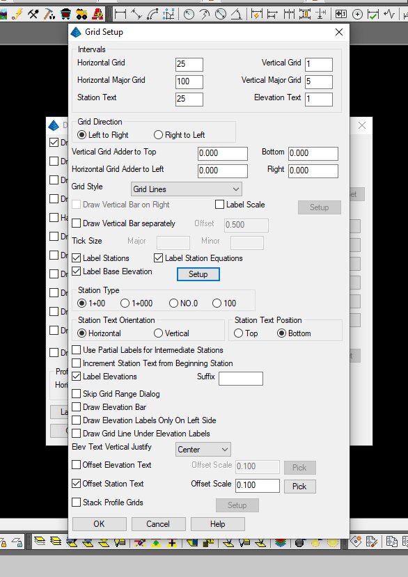
Adding elevations is good.


It is better to have the Top and Bottom start and end on Even numbers. For this, the entire station range is used.

Now you just place it. When you have more than one of the same it will ask if you want to delete the previous.

Once it is put into place, please make sure the profile line came out right. Sometimes the surface has a wrinkle that causes an anomaly. If your surface is perfect then your profile will be perfect… nothing is ever perfect.

There is an important thing to note - usually profiles are vertically exaggerated. This makes them tricky to work with. Here are some examples that help describe the exaggeration: https://www.ese-llc.com/tocbuilding-height-analysis